

How To Clear A Digital Thermometer
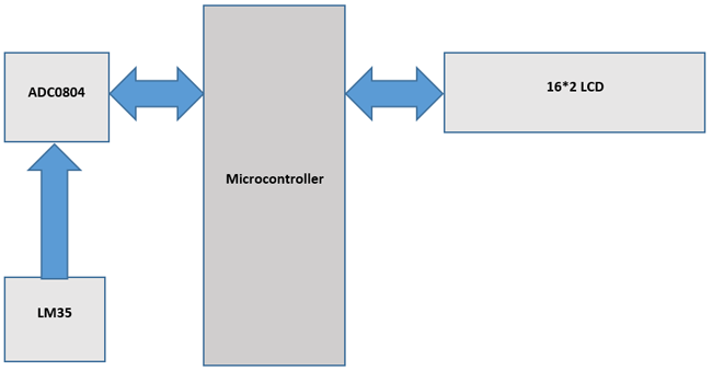
Sometimes people find it difficult to read temperature from analog thermometer because of fluctuations. So here we are going to build a simple Digital thermometer using 8051 microcontroller in which LM35 sensor is used for measuring the temperature. We have also used LM35 to build digital thermometer using Arduino, NodeMCU, PIC, Raspberry Pi and other microcontrollers.
This project will also serve as a proper interfacing of ADC0804 with 8051 and 16*2 LCD with 8051 microcontroller.
Components Required:
- 8051 development board
- ADC0804 board
- 16*2 LCD display
- LM35 sensor
- Potentiometer
- Jumper wires
Circuit Diagram:
Circuit diagram forDigital Thermometer Circuit using LM35 is given below:

Measuring Temperature with LM35 using 8051:
8051 microcontroller is a 8 bit microcontroller which has 128 bytes of on chip RAM , 4K bytes of on chip ROM, two timers, one serial port and four 8bit ports. 8052 microcontroller is an extension of microcontroller. The table below shows the comparison of 8051 family members.
| Feature | 8051 | 8052 |
| ROM (in bytes) | 4K | 8K |
| RAM (bytes) | 128 | 256 |
| Timers | 2 | 3 |
| I/O pins | 32 | 32 |
| Serial port | 1 | 1 |
| Interrupt sources | 6 | 8 |
16x2 LCD:
16*2 LCD is a widely used display for embedded applications. Here is the brief explanation about pins and working of 16*2 LCD display. There are two very important registers inside the LCD. They are data register and command register. Command register is used to send commands such as clear display, cursor at home etc., data register is used to send data which is to be displayed on 16*2 LCD. Below table shows the pin description of 16*2 lcd.
| Pin | Symbol | I/O | Description |
| 1 | Vss | - | Ground |
| 2 | Vdd | - | +5V power supply |
| 3 | Vee | - | Power supply to control contrast |
| 4 | RS | I | RS=0 for command register , RS=1 for data register |
| 5 | RW | I | R/W=0 for write , R/W=1 for read |
| 6 | E | I/O | Enable |
| 7 | D0 | I/O | 8-bit data bus(LSB) |
| 8 | D1 | I/O | 8-bit data bus |
| 9 | D2 | I/O | 8-bit data bus |
| 10 | D3 | I/O | 8-bit data bus |
| 11 | D4 | I/O | 8-bit data bus |
| 12 | D5 | I/O | 8-bit data bus |
| 13 | D6 | I/O | 8-bit data bus |
| 14 | D7 | I/O | 8-bit data bus(MSB) |
| 15 | A | - | +5V for backlight |
| 16 | K | - | Ground |
The below table shows frequently used LCD command codes.
| Code(hex) | Description |
| 01 | Clear display screen |
| 06 | Increment cursor (right shift) |
| 0A | Display off , cursor on |
| 0C | Display on , cursor off |
| 0F | Display on , cursor blinking |
| 80 | Force the cursor to beginning of 1st line |
| C0 | Force the cursor to beginning of 2nd line |
| 38 | 2 lines and 5*7 matrix |
ADC0804 IC:
The ADC0804 IC is an 8-bit parallel ADC in the family of the ADC0800 series from National Semiconductor. It works with +5 volts and has a resolution of 8bits. The step size and Vin range varies for different values of Vref/2. The table below shows the relation between Vref/2 and Vin range.
| Vref/2 (V) | Vin (V) | Step size (mV) |
| open | 0 to 5 | 19.53 |
| 2.0 | 0 to 4 | 15.62 |
| 1.5 | 0 to 3 | 11.71 |
| 1.28 | 0 to 2.56 | 10 |
In our case Vref/2 is connected to 1.28 volts, so step size is 10mV. For ADC0804 step size is calculated as (2 * Vref / 2) / 256.
Following formula is used to calculate output voltage:
Dout = Vin / step size
Where Dout is digital data output in decimal, Vin = analog input voltage and step size (resolution) is the smallest change. Learn more about ADC0804 here, also check interfacing of ADC0808 with 8051.
LM35 Temperature Sensor:
The LM35 is a temperature sensor whose output voltage is linearly proportional to Celsius temperature. The LM35 comes already calibrated hence requires no external calibration. It outputs 10mV for each degree of Celsius temperature.
LM35 sensor produces voltage corresponding to temperature. This voltage is converted to digital (0 to 256) by ADC0804 and it is fed to 8051 microcontroller. 8051 microcontroller converts this digital value into temperature in degree Celsius. Then this temperature is converted into ascii form which is suitable for displaying. This ascii values are fed to 16*2 lcd which displays the temperature on its screen. This process is repeated after specified interval.
Below is the setup image forLM35 Digital Thermometer using 8051:
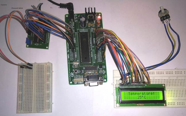
You can find all the LM35 based digital thermometers here.
Code explanation:
The complete C program for this Digital Thermometer using LM35 is given at the end of this project. The code is split into small meaningful chunks and explained below.
For 16*2 LCD interfacing with 8051 microcontroller , we have to define pins on which 16*2 lcd is connected to 8051 microcontroller. RS pin of 16*2 lcd is connected to P2.7 , RW pin of 16*2 lcd is connected to P2.6 and E pin of 16*2 lcd is connected to P2.5. Data pins are connected to port 0 of 8051 microcontroller.
sbit rs=P2^7; //Register Select(RS) pin of 16*2 lcd sbit rw=P2^6; //Read/Write(RW) pin of 16*2 lcd sbit en=P2^5; //Enable(E) pin of 16*2 lcd
Similarly, for ADC0804 interfacing with 8051 microcontroller, we have to define pins on which ADC0804 is connected to 8051 microcontroller. RD pin of ADC0804 is connected to P3.0, WR pin of ADC0804 is connected to P3.1 and INTR pin of ADC0804 is connected to P3.2. Data pins are connected to port 1 of 8051 microcontroller.
sbit rd_adc=P3^0; //Read(RD) pin of ADC0804 sbit wr_adc=P3^1; //Write(WR) pin of ADC0804 sbit intr_adc=P3^2; //Interrupt(INTR) pin of ADC0804
Next we have to define some functions which are used in the program. Delay function is used to create specified time delay, cmdwrt function is used to send commands to 16*2 lcd display, datawrt function is used to send data to 16*2 lcd display and convert_display function is used to convert the ADC data into temperature and to display it on 16*2 lcd display.
void delay(unsigned int) ; //function for creating delay void cmdwrt(unsigned char); //function for sending commands to 16*2 lcd display void datawrt(unsigned char); //function for sending data to 16*2 lcd display void convert_display(unsigned char); //function for converting ADC value to temperature and display it on 16*2 lcd display
In below part of the code, we are sending commands to 16*2 lcd. Commands such as clear display, increment cursor, force the cursor to beginning of 1st line are sent to 16*2 lcd display one by one after some specified time delay.
for(i=0;i<5;i++) //send commands to 16*2 lcd display one command at a time { cmdwrt(cmd[i]); //function call to send commands to 16*2 lcd display delay(1); } In this part of the code, we are sending data to 16*2 lcd. Data to be displayed on 16*2 lcd display are sent to display one by one after some specified time delay.
for(i=0;i<12;i++) //send data to 16*2 lcd display one character at a time { datawrt(data1[i]); //function call to send data to 16*2 lcd display delay(1); } In this part of the code we are converting the analog voltage produced by LM35 sensor to digital data and then it is converted to temperature and displayed on 16*2 lcd display. For ADC0804 to start the conversion we have to send a low to high pulse on WR pin of ADC0804, then we have to wait for end of conversion. INTR becomes low at the end of conversion. Once INTR becomes low, RD is made low to copy the digital data to port 0 of 8051 microcontroller. After a specified time delay, next cycle starts. This process is repeated forever.
while(1) //repeat forever { wr_adc=0; //send LOW to HIGH pulse on WR pin delay(1); wr_adc=1; while(intr_adc==1); //wait for End of Conversion rd_adc=0; //make RD = 0 to read the data from ADC0804 value=P1; //copy ADC data convert_display(value); //function call to convert ADC data into temperature and display it on 16*2 lcd display delay(1000); //interval between every cycles rd_adc=1; //make RD = 1 for the next cycle } In below part of the code , we are sending commands to 16*2 lcd display. The command is copied to port 0 of 8051 microcontroller. RS is made low for command write. RW is made low for write operation. High to low pulse is applied on enable(E) pin to start command write operation.
void cmdwrt (unsigned char x) { P0=x; //send the command to Port 0 on which 16*2 lcd is connected rs=0; //make RS = 0 for command rw=0; //make RW = 0 for write operation en=1; //send a HIGH to LOW pulse on Enable(E) pin to start commandwrite operation delay(1); en=0; } In this part of the code, we are sending data to 16*2 lcd display. The data is copied to port 0 of 8051 microcontroller. RS is made high for command write . RW is made low for write operation. High to low pulse is applied on enable(E) pin to start data write operation.
void datawrt (unsigned char y) { P0=y; //send the data to Port 0 on which 16*2 lcd is connected rs=1; //make RS = 1 for command rw=0; //make RW = 0 for write operation en=1; //send a HIGH to LOW pulse on Enable(E) pin to start datawrite operation delay(1); en=0; } In this part of the code, we are converting digital data into temperature and displaying it on 16*2 lcd display.
void convert_display(unsigned char value) { unsigned char x1,x2,x3; cmdwrt(0xc6); //command to set the cursor to 6th position of 2nd line on 16*2 lcd x1=(value/10); //divide the value by 10 and store quotient in variable x1 x1=x1+(0x30); //convert variable x1 to ascii by adding 0x30 x2=value%10; //divide the value by 10 and store remainder in variable x2 x2=x2+(0x30); //convert variable x2 to ascii by adding 0x30 x3=0xDF; //ascii value of degree(°) symbol datawrt(x1); //display temperature on 16*2 lcd display datawrt(x2); datawrt(x3); datawrt('C'); } Also, check other thermometers using LM35 with different microcontrollers:
- Digital Thermometer using Arduino and LM35
- Temperature Measurement using LM35 and AVR Microcontroller
- Room Temperature Measurement with Raspberry Pi
Code
/*this program is for displaying the temperature on 16*2 lcd display using 8051 microcontroller , LM35 sensor and ADC0804*/
#include<reg51.h>
sbit rs=P2^7; //Register Select(RS) pin of 16*2 lcd
sbit rw=P2^6; //Read/Write(RW) pin of 16*2 lcd
sbit en=P2^5; //Enable(E) pin of 16*2 lcd
sbit rd_adc=P3^0; //Read(RD) pin of ADC0804
sbit wr_adc=P3^1; //Write(WR) pin of ADC0804
sbit intr_adc=P3^2; //Interrupt(INTR) pin of ADC0804
void delay(unsigned int) ; //function for creating delay
void cmdwrt(unsigned char); //function for sending commands to 16*2 lcd display
void datawrt(unsigned char); //function for sending data to 16*2 lcd display
void convert_display(unsigned char); //function for converting ADC value to temperature and display it on 16*2 lcd display
void main(void) //main function
{
unsigned char i;
unsigned char cmd[]={0x38,0x01,0x06,0x0c,0x82};//16*2 lcd initialization commands
unsigned char data1[]="Temperature:";
unsigned char value;
P1=0xFF; //make Port 1 as input port
P0=0x00; //make Port 0 as output port
for(i=0;i<5;i++) //send commands to 16*2 lcd display one command at a time
{
cmdwrt(cmd[i]); //function call to send commands to 16*2 lcd display
delay(1);
}
for(i=0;i<12;i++) //send data to 16*2 lcd display one character at a time
{
datawrt(data1[i]); //function call to send data to 16*2 lcd display
delay(1);
}
intr_adc=1; //make INTR pin as input
rd_adc=1; //set RD pin HIGH
wr_adc=1; //set WR pin LOW
while(1) //repeat forever
{
wr_adc=0; //send LOW to HIGH pulse on WR pin
delay(1);
wr_adc=1;
while(intr_adc==1); //wait for End of Conversion
rd_adc=0; //make RD = 0 to read the data from ADC0804
value=P1; //copy ADC data
convert_display(value); //function call to convert ADC data into temperature and display it on 16*2 lcd display
delay(1000); //interval between every cycles
rd_adc=1; //make RD = 1 for the next cycle
}
}
void cmdwrt (unsigned char x)
{
P0=x; //send the command to Port 0 on which 16*2 lcd is connected
rs=0; //make RS = 0 for command
rw=0; //make RW = 0 for write operation
en=1; //send a HIGH to LOW pulse on Enable(E) pin to start commandwrite operation
delay(1);
en=0;
}
void datawrt (unsigned char y)
{
P0=y; //send the data to Port 0 on which 16*2 lcd is connected
rs=1; //make RS = 1 for command
rw=0; //make RW = 0 for write operation
en=1; //send a HIGH to LOW pulse on Enable(E) pin to start datawrite operation
delay(1);
en=0;
}
void convert_display(unsigned char value)
{
unsigned char x1,x2,x3;
cmdwrt(0xc6); //command to set the cursor to 6th position of 2nd line on 16*2 lcd
x1=(value/10); //divide the value by 10 and store quotient in variable x1
x1=x1+(0x30); //convert variable x1 to ascii by adding 0x30
x2=value%10; //divide the value by 10 and store remainder in variable x2
x2=x2+(0x30); //convert variable x2 to ascii by adding 0x30
x3=0xDF; //ascii value of degree(°) symbol
datawrt(x1); //display temperature on 16*2 lcd display
datawrt(x2);
datawrt(x3);
datawrt('C');
}
void delay(unsigned int z)
{
unsigned int p,q;
for(p=0;p<z;p++) //repeat for 'z' times
{
for(q=0;q<1375;q++); //repeat for 1375 times
}
}
How To Clear A Digital Thermometer
Source: https://circuitdigest.com/microcontroller-projects/digital-thermometer-using-lm35-8051/
Posted by: brottneves1942.blogspot.com
0 Response to "How To Clear A Digital Thermometer"
Post a Comment